Basic IS-IS Level2 Only Cisco Lab Configuration
Configuration guide utilizing Cisco Modeling Lab to build a 4 router is-is networking topology.
758 Words
2021-02-26 10:42 -0600
Overview
A foundational component of any large networking environment is the infrastructure routes, or said another way, the network routes that allow each router to find and communicate with one another. The most common routing protocols to distribute internal network routes are ospf, is-is, and eigrp. In this post I will use Cisco Modeling Lab to build a basic 4 router topology using is-is as the infrastructure routing protocol.
Lab Topology Diagrams
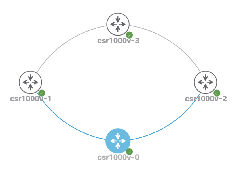
The Cisco Modeling Lab topology:
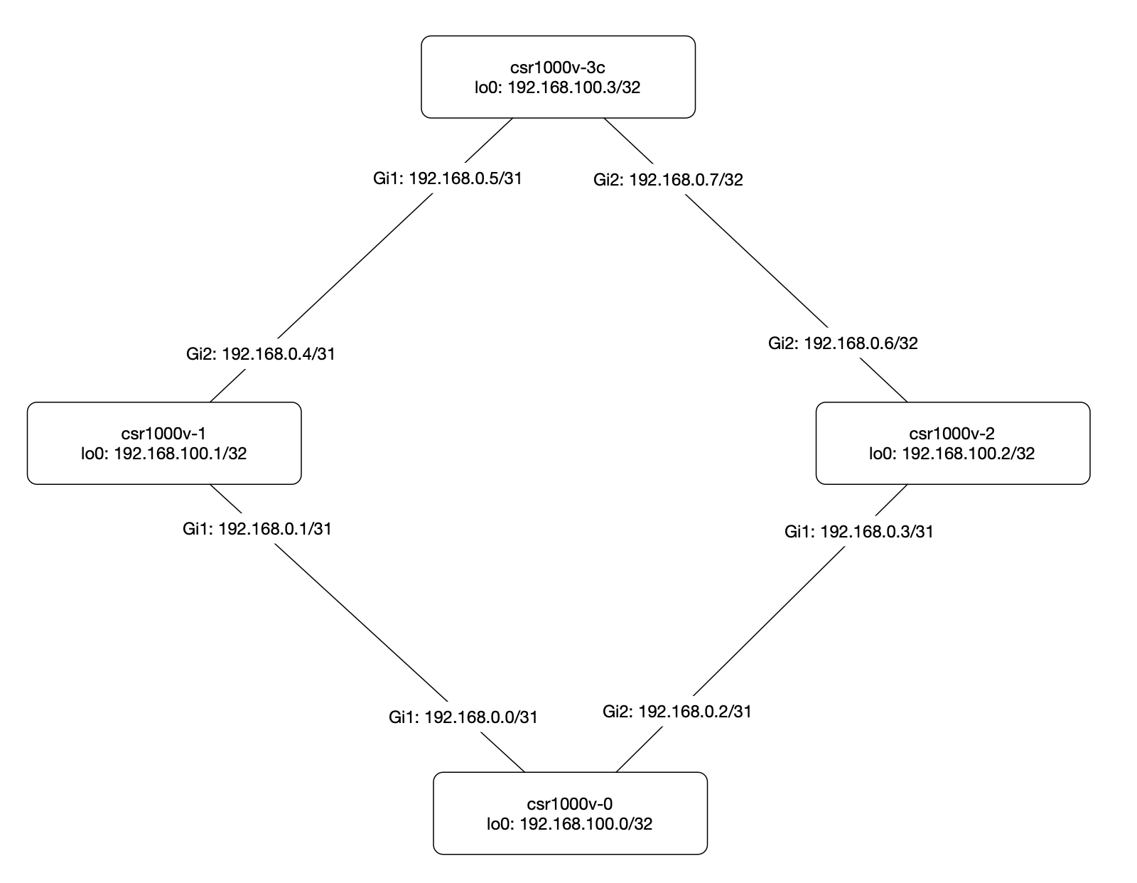
Logical topology with name and addressing information:
Template Configurations
Each router is built with a configuration similar to the one below.
- Global configuration to enable the
is-isrouting protocol. The instance is namedlabisisfor later reference or if multiple instances are used on the same device. - The
netID uniquely identifies each router and sets the area:- 49 — AFI
- 0000 — Area ID
- 0000.0000.0000 — System identifier (unique for each device, typically in an IP address format)
- 00 — Selector
is-type level-2-only- All routers behave like abackbonerouter allowing communication with other areas if needed.metric-style wide- Allows for greater flexibility when traffic engineering.ip router isis labisis- Enableis-ison a network interface.
router isis labisis
 net 49.0000.0000.0003.00
 is-type level-2-only
 metric-style wide

interface Loopback0
 ip router isis labisis
!
interface GigabitEthernet1
 ip router isis labisis

interface GigabitEthernet2
 ip router isis labisis
Router Configurations
csr1000v-0
Router configuration:
interface Loopback0
 ip address 192.168.100.0 255.255.255.255
 ip router isis labisis
!
interface GigabitEthernet1
 description to GigabitEthernet1.csr1000v-1
 ip address 192.168.0.0 255.255.255.254
 ip router isis labisis
!
interface GigabitEthernet2
 description to GigabitEthernet1.csr1000v-2
 ip address 192.168.0.2 255.255.255.254
 ip router isis labisis
!
router isis labisis
 net 49.0000.0000.0000.00
 is-type level-2-only
 metric-style wide
csr1000v-1
Router configuration:
interface Loopback0
 ip address 192.168.100.1 255.255.255.255
 ip router isis labisis
!
interface GigabitEthernet1
 description to GigabitEthernet1.csr1000v-0
 ip address 192.168.0.1 255.255.255.254
 ip router isis labisis
!
interface GigabitEthernet2
 description to GigabitEthernet1.csr1000v-3
 ip address 192.168.0.4 255.255.255.254
 ip router isis labisis
!
router isis labisis
 net 49.0000.0000.0001.00
 is-type level-2-only
 metric-style wide
csr1000v-2
Router configuration:
interface Loopback0
 ip address 192.168.100.2 255.255.255.255
 ip router isis labisis
!
interface GigabitEthernet1
 description to GigabitEthernet2.csr1000v-0
 ip address 192.168.0.3 255.255.255.254
 ip router isis labisis
!
interface GigabitEthernet2
 description to GigabitEthernet2.csr1000v-3
 ip address 192.168.0.6 255.255.255.254
 ip router isis labisis
!
router isis labisis
 net 49.0000.0000.0002.00
 is-type level-2-only
 metric-style wide
csr1000v-3
Router configuration:
interface Loopback0
 ip address 192.168.100.3 255.255.255.255
 ip router isis labisis
!
interface GigabitEthernet1
 description to GigabitEthernet2.csr1000v-1
 ip address 192.168.0.5 255.255.255.254
 ip router isis labisis
!
interface GigabitEthernet2
 description to GigabitEthernet2.csr1000v-2
 ip address 192.168.0.7 255.255.255.254
 ip router isis labisis
!
router isis labisis
 net 49.0000.0000.0003.00
 is-type level-2-only
 metric-style wide
Testing and Validation
Validate IS-IS neighbors:
csr1000v-0#show isis neighbors

Tag labisis:
System Id       Type Interface     IP Address      State Holdtime Circuit Id
csr1000v-1      L2   Gi1           192.168.0.1     UP    25       csr1000v-0.01
csr1000v-2      L2   Gi2           192.168.0.3     UP    29       csr1000v-0.02
Validate infrastructure interfaces are in the routing table:
csr1000v-0#show ip route
Codes: L - local, C - connected, S - static, R - RIP, M - mobile, B - BGP
       D - EIGRP, EX - EIGRP external, O - OSPF, IA - OSPF inter area
       N1 - OSPF NSSA external type 1, N2 - OSPF NSSA external type 2
       E1 - OSPF external type 1, E2 - OSPF external type 2, m - OMP
       n - NAT, Ni - NAT inside, No - NAT outside, Nd - NAT DIA
       i - IS-IS, su - IS-IS summary, L1 - IS-IS level-1, L2 - IS-IS level-2
       ia - IS-IS inter area, * - candidate default, U - per-user static route
       H - NHRP, G - NHRP registered, g - NHRP registration summary
       o - ODR, P - periodic downloaded static route, l - LISP
       a - application route
       + - replicated route, % - next hop override, p - overrides from PfR

Gateway of last resort is not set

      192.168.0.0/24 is variably subnetted, 6 subnets, 2 masks
C        192.168.0.0/31 is directly connected, GigabitEthernet1
L        192.168.0.0/32 is directly connected, GigabitEthernet1
C        192.168.0.2/31 is directly connected, GigabitEthernet2
L        192.168.0.2/32 is directly connected, GigabitEthernet2
i L2     192.168.0.4/31 [115/20] via 192.168.0.1, 00:12:56, GigabitEthernet1
i L2     192.168.0.6/31 [115/20] via 192.168.0.3, 00:12:22, GigabitEthernet2
      192.168.100.0/32 is subnetted, 4 subnets
C        192.168.100.0 is directly connected, Loopback0
i L2     192.168.100.1 [115/20] via 192.168.0.1, 00:09:25, GigabitEthernet1
i L2     192.168.100.2 [115/20] via 192.168.0.3, 00:12:22, GigabitEthernet2
i L2     192.168.100.3 [115/30] via 192.168.0.3, 00:11:52, GigabitEthernet2
                       [115/30] via 192.168.0.1, 00:11:52, GigabitEthernet1
Validate connectivity from router 0 to 3:
csr1000v-0#ping 192.168.100.3
Type escape sequence to abort.
Sending 5, 100-byte ICMP Echos to 192.168.100.3, timeout is 2 seconds:
!!!!!
Success rate is 100 percent (5/5), round-trip min/avg/max = 2/17/78 ms

